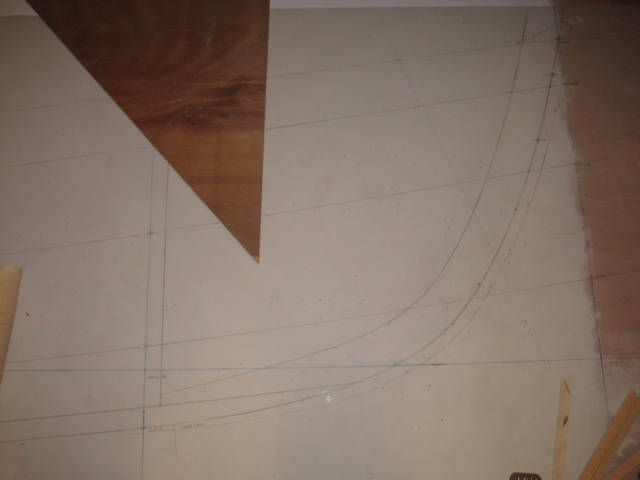
Fox Island Class Sloop - Lofting
|
0 - To start small, the lofting began with the fin keel which was mostly independent of the rest of the lofting. Yes, that is the dining room floor... |
|
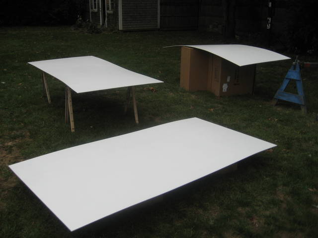
1 - The profile and half-breadth plan required three sheets of plywood. Here are three sheets of luan being painted white. |
|
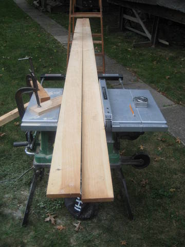
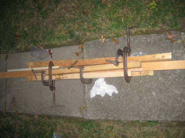
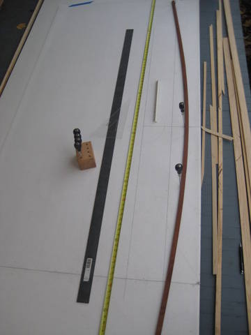
2 - The profile and half-breadth plans also would require some long battens for the sheer, keel, plank laps, etc. A really nice 16' white pine board with pretty straight grain was ripped for batten stock. |
|
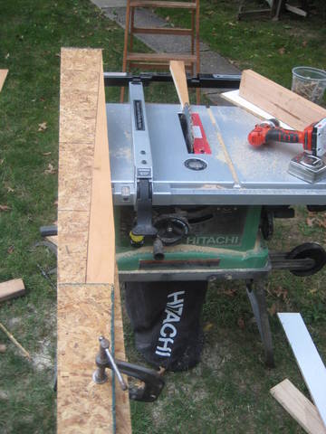
3 - The 16' pieces needed a scarf to be long enough for the 22' boat. |
|
4 - Gluing up the scarf with scrap used to keep everything in line. |
|
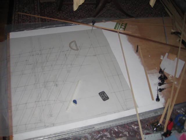
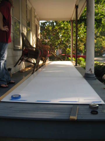
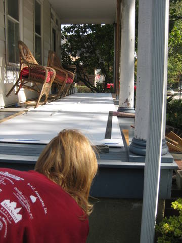
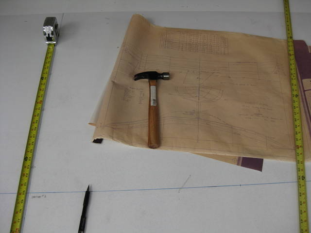
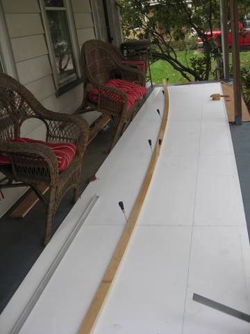
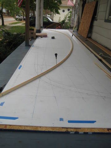
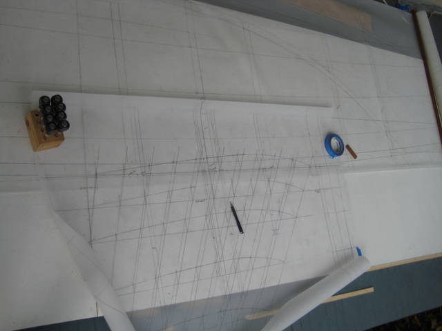
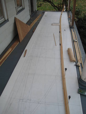
5 - The front porch was the best location at hand for lofting the boat and offered a convient working height. The luan was set on top of some wafer board to protect the porch floor from the nails and awls which will go through the luan. Here the boss (my next door neighbor calls her "The Captain") gives everything a look. |
|
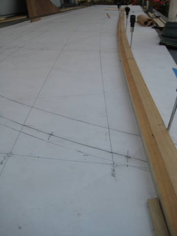
6 - The lofting was done on mylar film rolled out on top of the plywood - all the drawing was done on the mylar. The first step was to lay down the baseline for the profile which is also the DWL. |
|
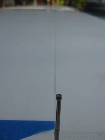
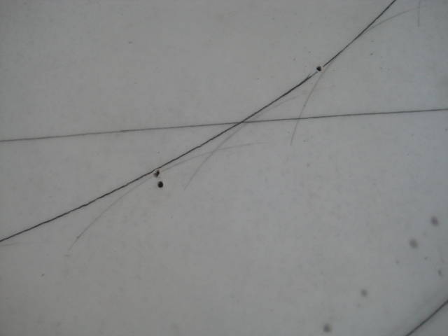
7 - A monofilament line was stretched very tight and then marks were put down using a spacer block. Doing it this way eliminates the liklihood of parallelax from having the line too far above the surface, but also allows the line to be high enough to not touch the surface even if there are slight variations in height along the length of the line. |
|
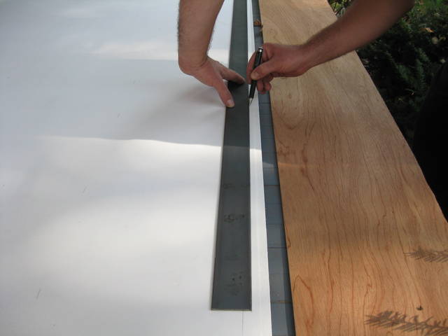
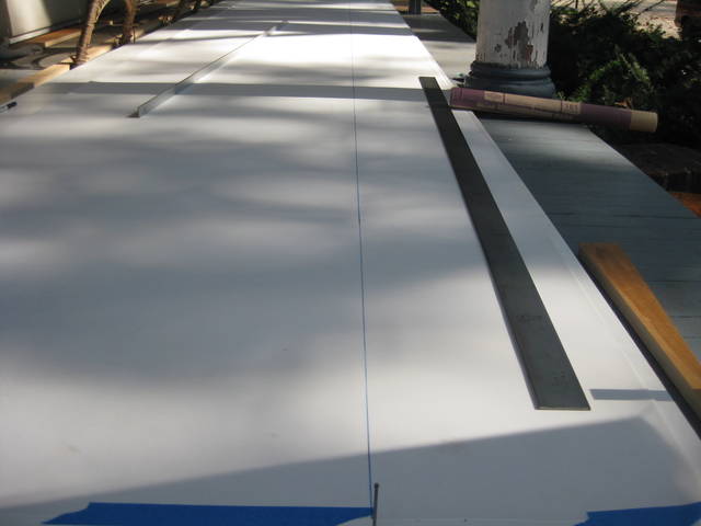
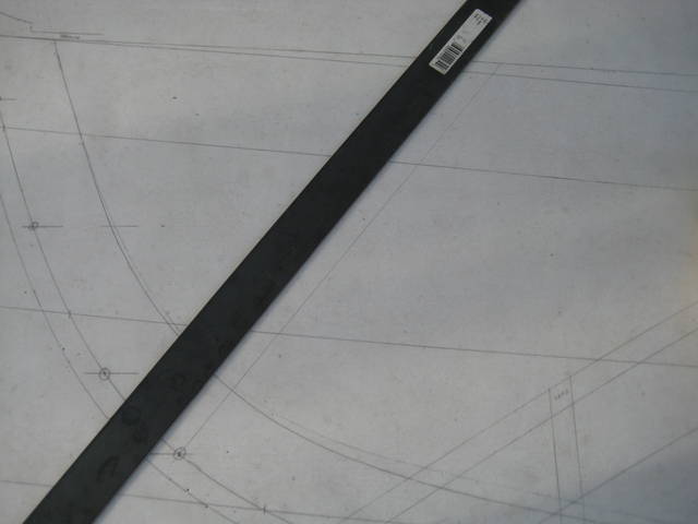
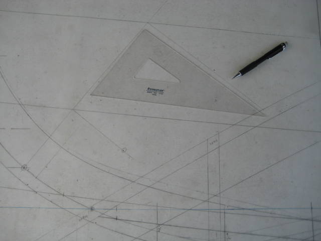
8 - The straight edge should be checked for straightness by drawing a line and then flipping the edge over and verifying that the edge still matches the line just drawn. In this case the straight edge was not good so we picked up a piece of flat steel. |
|
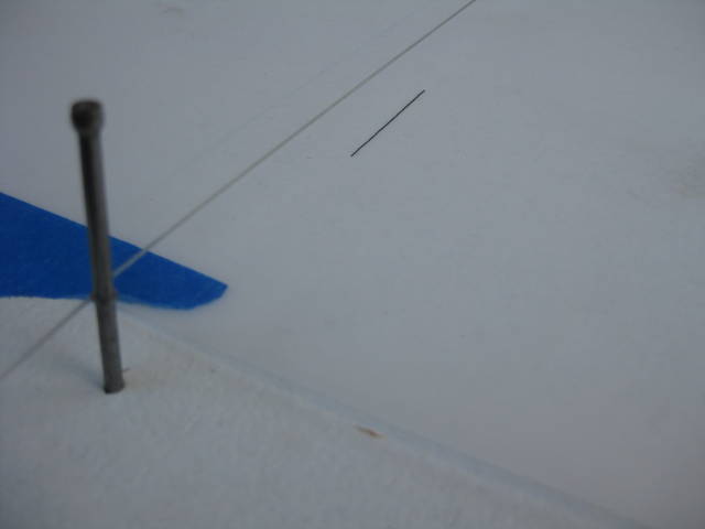
9 - Once the individual marks are put down along the length of the line, the DWL is struck using a straight edge to "connect the dots." |
|
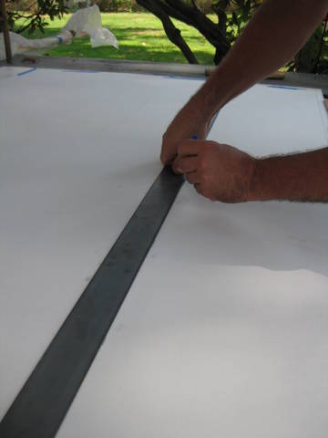
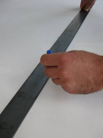
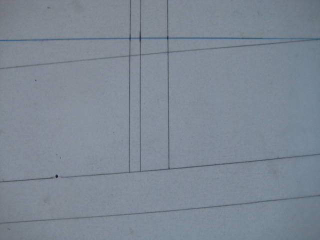
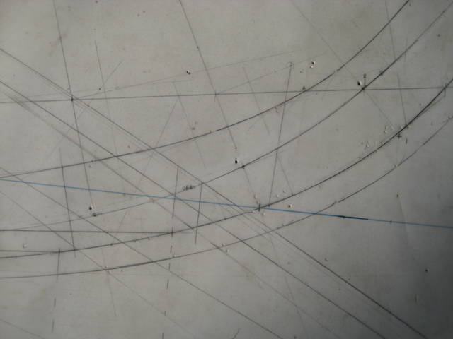
10 - A blue permanent marker was used for the DWL and station lines so that they would stand out. In addition, after these lines were drawn the mylar sheet was flipped over and all the remaining drawing was done on the other side so that the "fixed" lines would never be erased. |
|
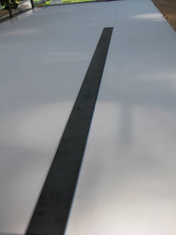
11 - An almost-complete DWL. |
|
12 - Sight the line for straightness. |
|
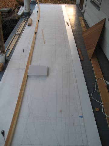
13 - The line is complete. This also shows how the mylar was taped down when lofting with blue painter's tape. |
|
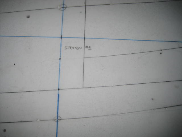
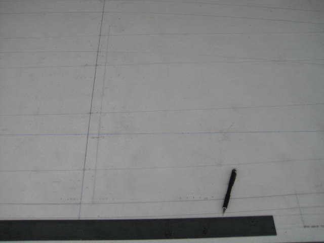
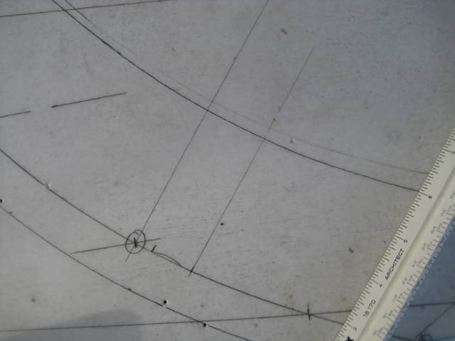
14 - Using a square (check this for accuracy too), the station lines are laid down. |
|
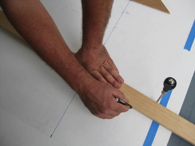
15 - Once the baseline and stations are done, it is encouraging to begin using the table of offsets and lines plan to begin laying out the profile of the boat. Here the stem profile and laps lines at the stem are being marked. |
|
16 - Near the stem head. |
|
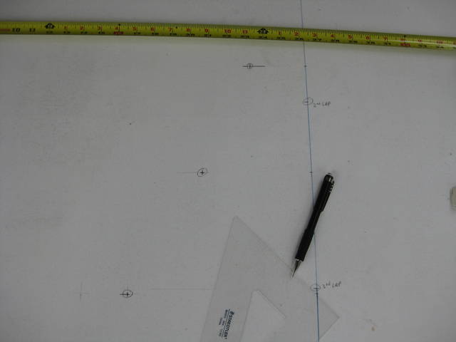
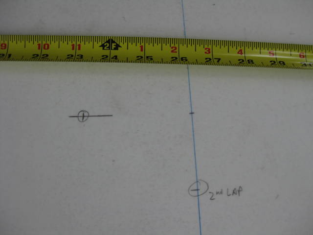
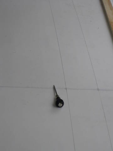
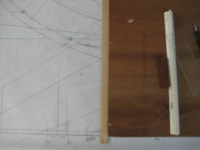
17 - The heights above the baseline (DWL in this case) are being marked. No, it is not good to use two different tape measures. |
|
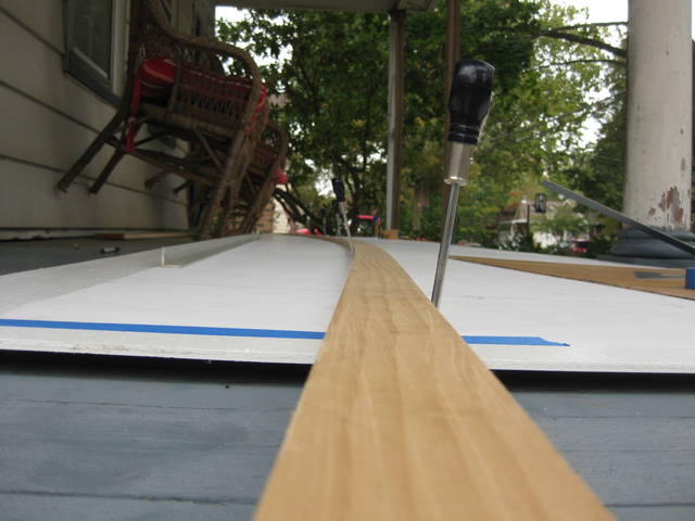
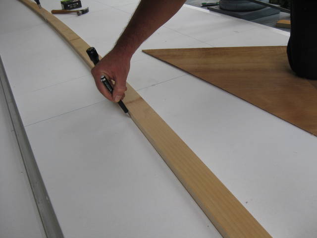
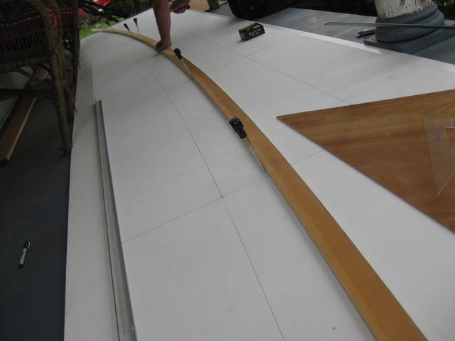
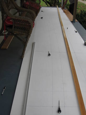
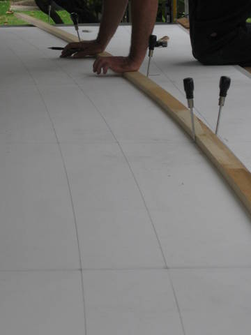
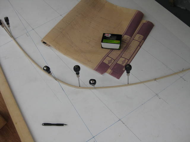
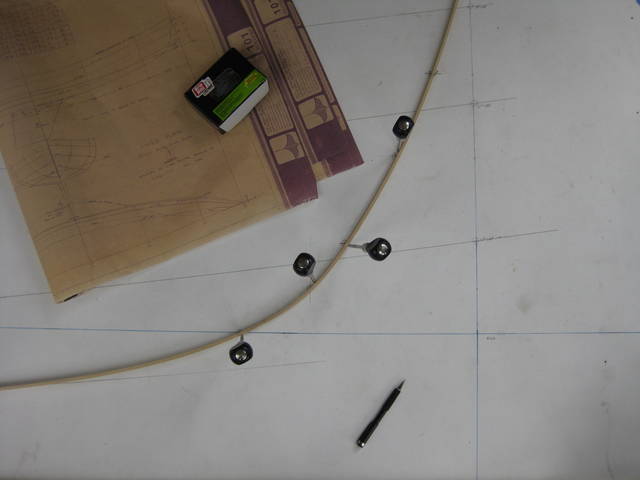
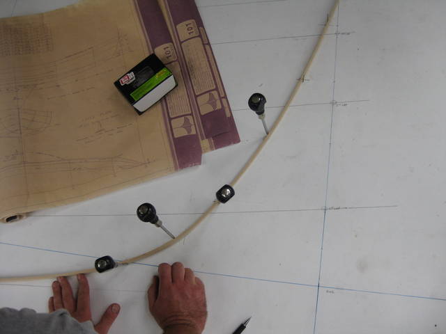
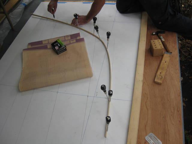
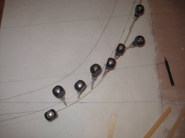
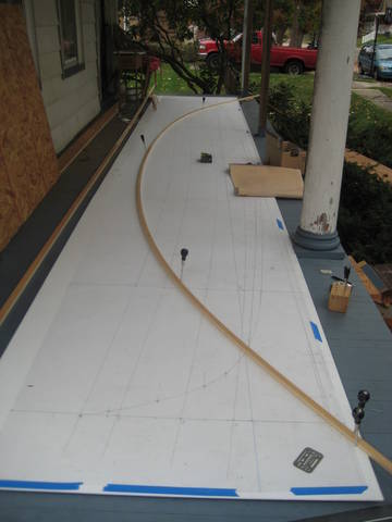
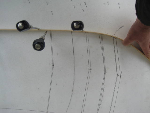
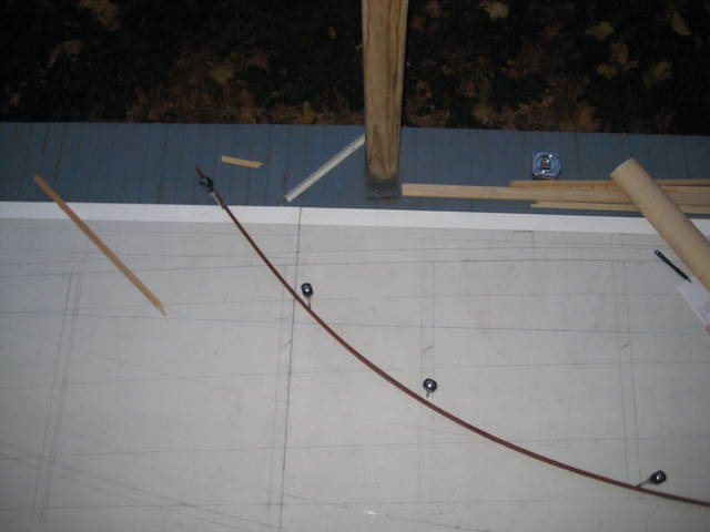
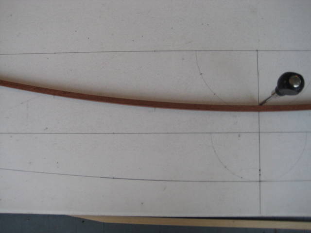
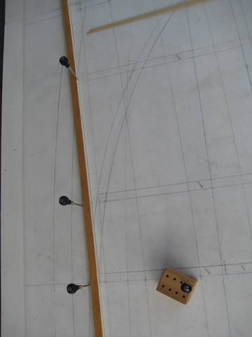
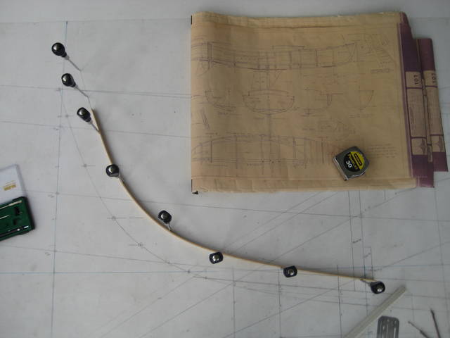
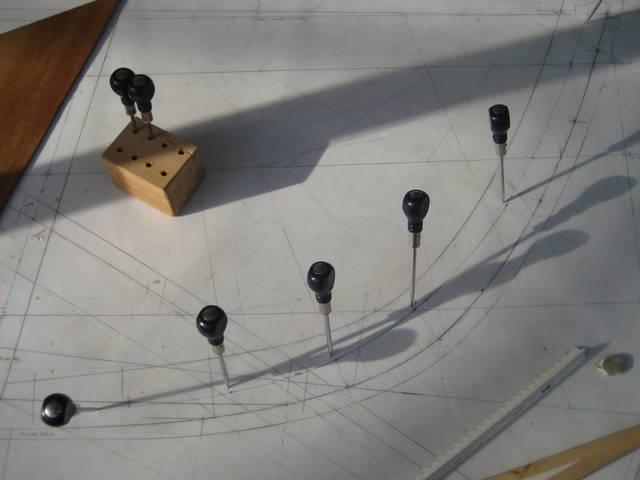
18 - A nice wide batten is used for laying down the sheer. A set of 8 awls was used for positioning the batten. |
|
19 - It is fun to start seeing the sheer line. |
|
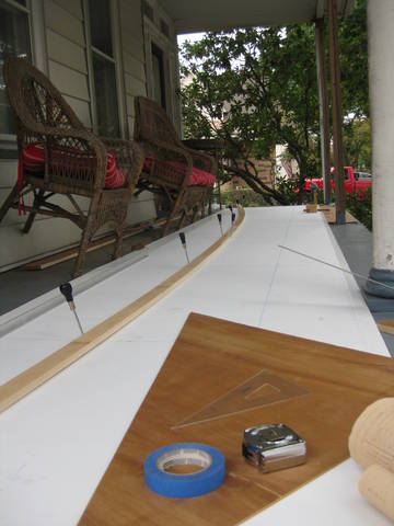
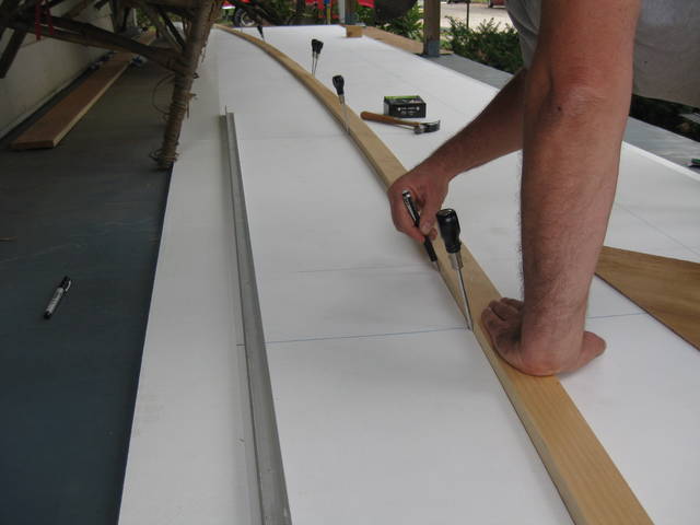
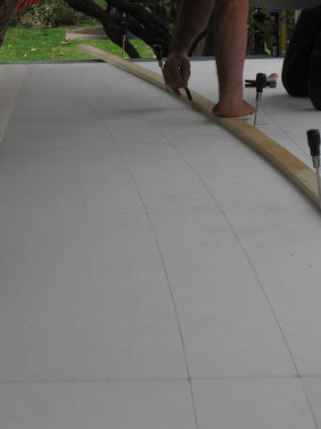
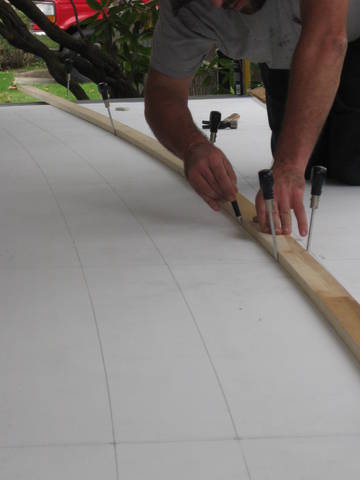
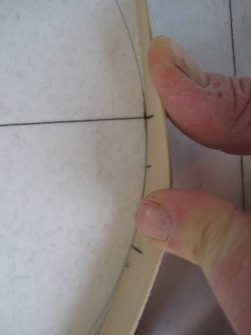
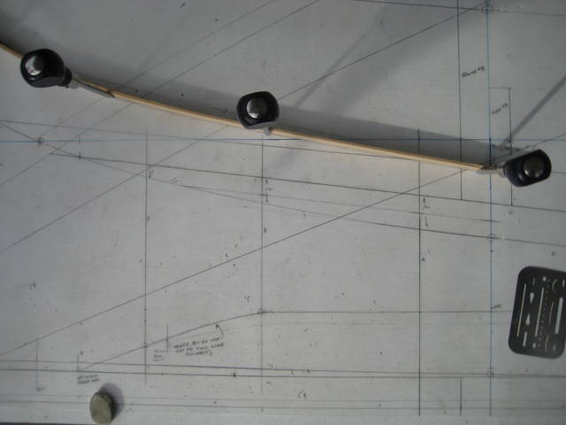
20 - Time to see if the curve looks fair. In this case the awls on both sides of the batten indicate that something is being forced that shouldn't be. |
|
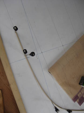
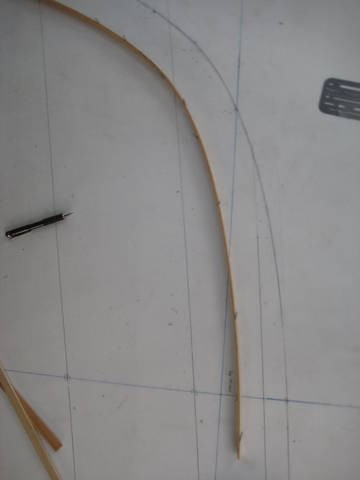
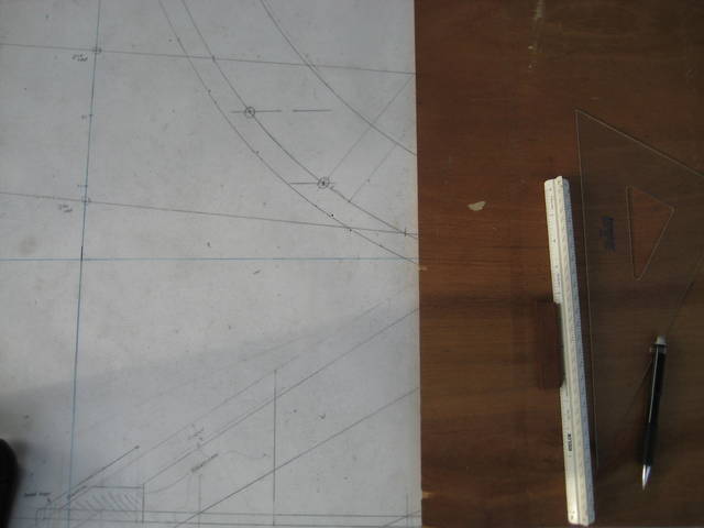
21 - Once everything looks ok, strike the line. A 0.5mm pencil was used for pretty much everything after the blue lines were marked. |
|
22 - Marking the sheer. |
|
23 - More marking of the sheer. (It was the first line so lots of pictures...) |
|
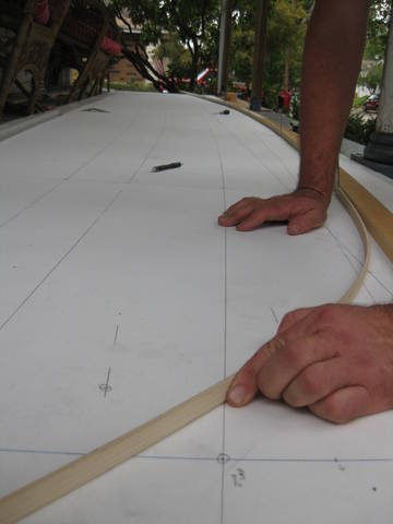
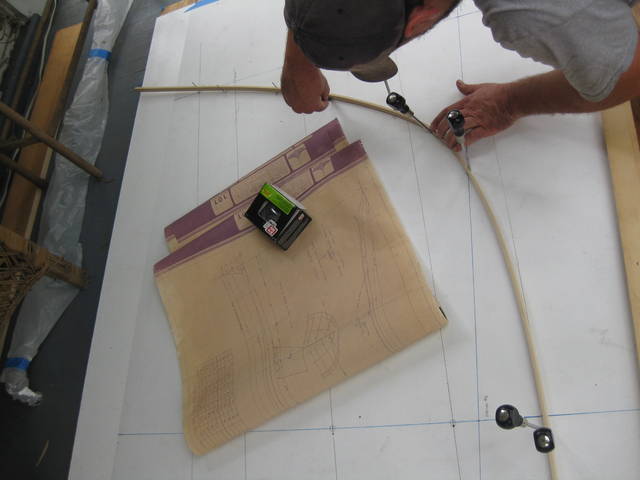
24 - Similar to the sheer, the first lap line is drawn next. |
|
25 - These two lines can be seen together here. |
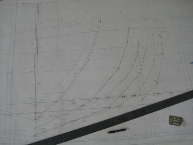
|
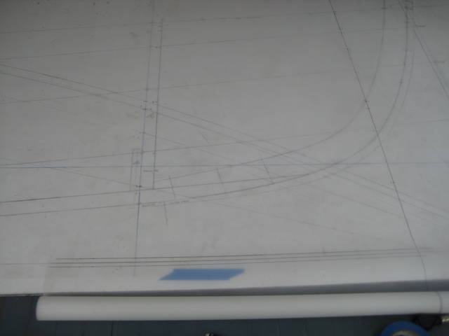
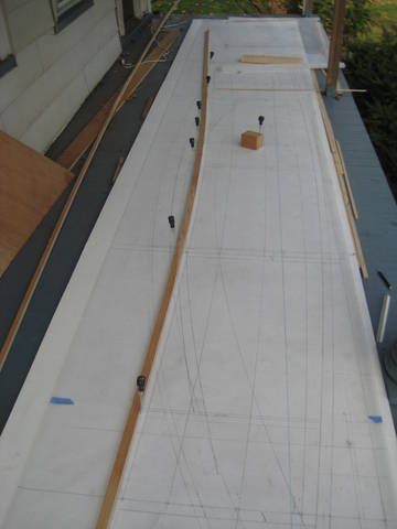
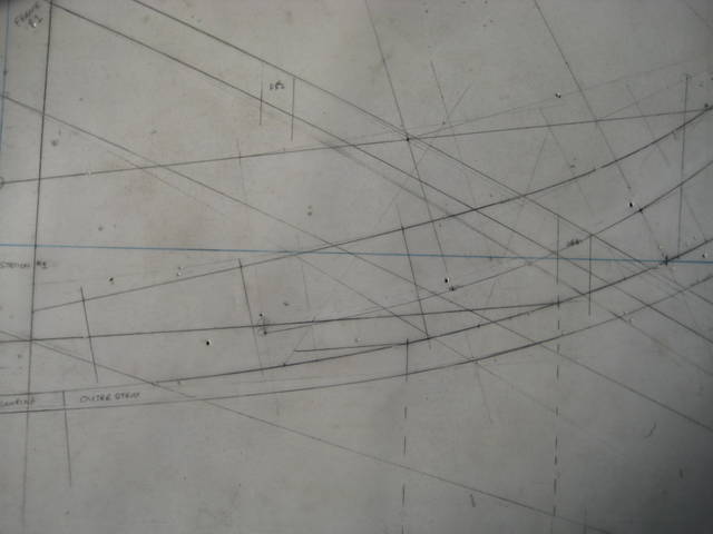
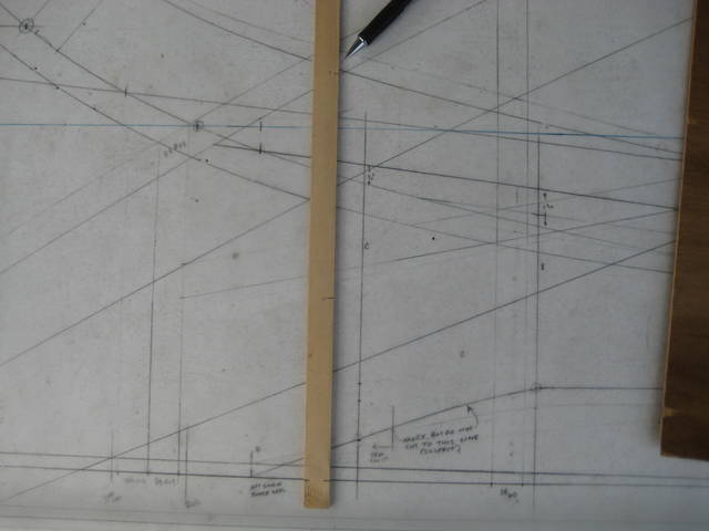
26 - Same two lines, but the full length. |
|
27 - Drawing the second lap. |
|
28 - More drawing the second lap. |
|
29 - Even more drawing the second lap... |
|
30 - The stern stem is being transitioned into the keel. |
|
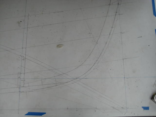
31 - The bow stem is being laid out. |
|
32 - The stern stem was drawn once and quickly, but the bow stem was drawn a couple of times because it took a while to look right. |
|
33 - Another iteration of the bow stem. |
|
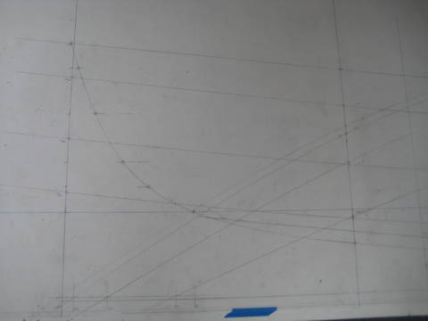
34 - The bow stem being transitioned onto the plank keel. |
|
35 - One of many stem iterations. |
|
36 - More of the bow stem. |
|
37 - Laying out the molded depth of the stem. |
|
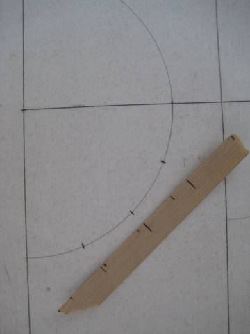
38 - The molded depth was set by using a compass to set the distance. |
|
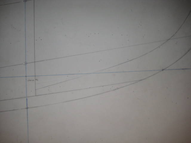
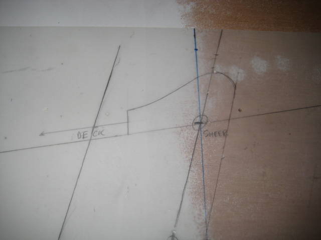
39 - The inner stem at station #1 / frame #1, showing how it tapers down as it goes above the plank keel. |
|
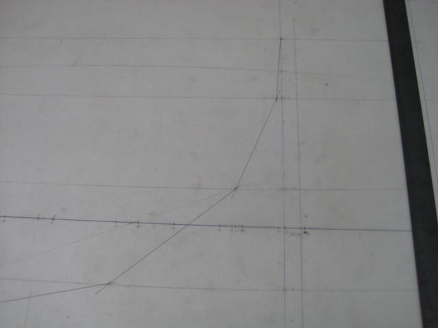
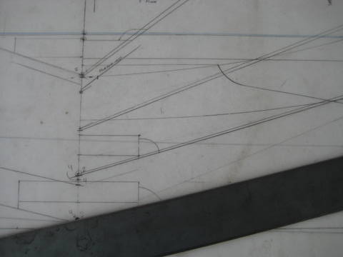
40 - The forward bulkhead and bulhead blocking at the keel. |
|
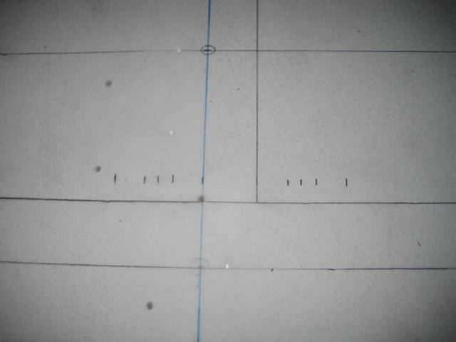
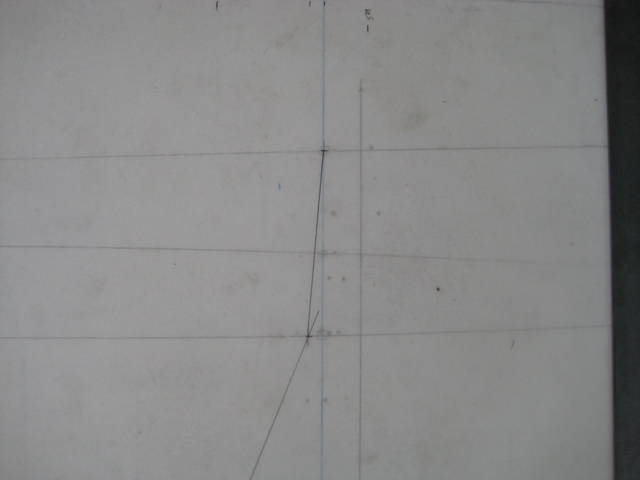
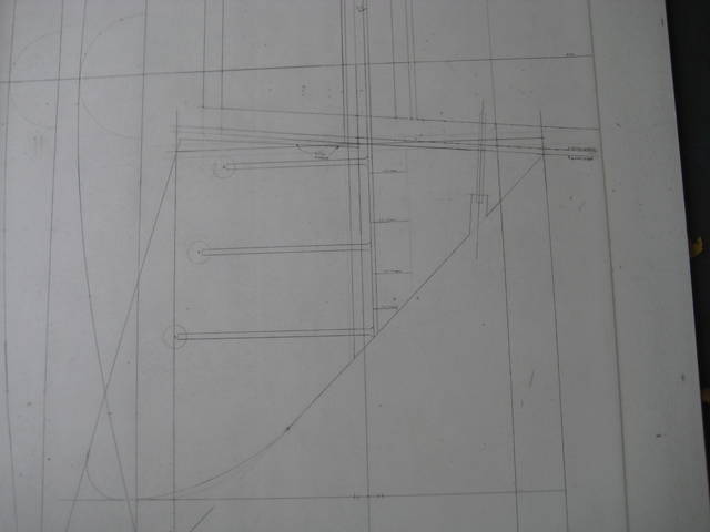
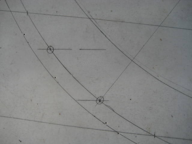
41 - Here the floors are being laid out along side a frame. The three marks on either side of the frame are the keel bolts (outside and centerline). |
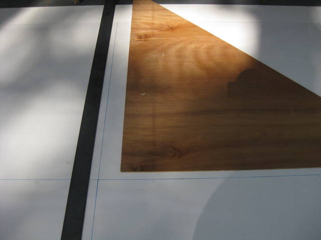
|
42 - A little wider view of the bow/keel. |
|
43 - The outer stem/capping is also laid out. |
|
44 - The stemhead being worked out. |
|
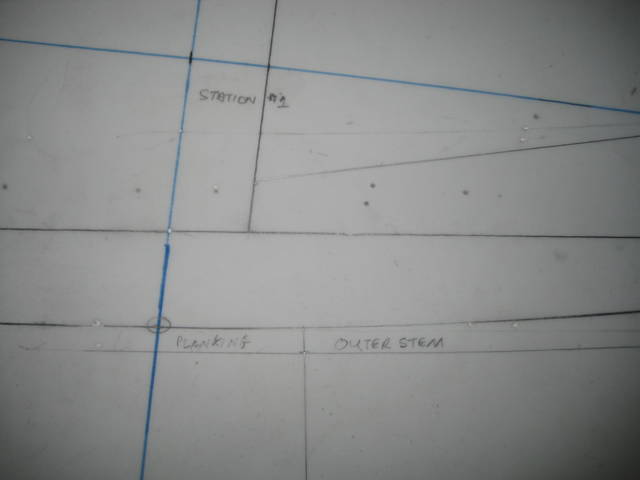
45 - The outer stem/capping needs to transition smoothly into the planking near station #1 / frame #1. |
|
46 - A little wider view of the bow. |
|
47 - After working on the profile, it is time to start the half-breadth plan. The half-breadth plan was laid out on the same sheet as the profile, but with a separate baseline. Having it on the same sheet makes keeping the two views in sync easier. |
|
48 - More of the half-breadth. |
|
49 - The lap lines in half-breadth view terminate on the inner stem face which is 3/4" wide on the face (3/8" wide in half-breadth). |
|
50 - Stern view of the same thing. |
|
51 - Both profile and half-breadth near the fin keel. |
|
52 - The foward-most floor and stem-keel bolts are added. |
|
53 - One station of the body plan is complete. Instead of using pick-up sticks to lay out the body plan, the mylar allows the body plan to be laid out by putting the body plan sheet on top of the profile and half-breadth sheet to pick up the dimensions directly. I don't think it is much faster, but points only have to marked once instead of twice so it should be more accurate. |
|
54 - A closer view of the sheer on a body plan station. The profile / half-breadth sheet can be seen underneath. |
|
55 - The body plan is a little more developed at this point. On the DWL the marks can be seen that are taken off of the half-breadth plan at each station and labled. Then the body plan is rotated as shown here and the heights are marked off with each half-breadth mark lined up on the station line. |
|
56 - The keel sections have to be laid out on the body plan so that the keel taper can be subsequently laid out on the half-breadth plan. |
|
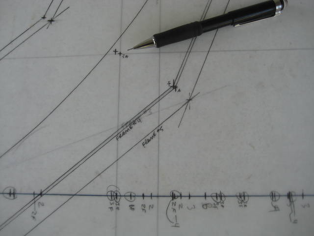
57 - Except for frames 5 and 6 in the middle of the boat, the fore and aft side of each frame and bulkhead is put on the body plan. By lining up the half-breadth marks on the station line and lining up the DWLs on the body plan and profile plan, the lap line intersections can be marked without any use of a square and with only one other mark being made. |
|
58 - The sheer line is being drawn on the body plan. I don't think the fore-aft lines in this view are really useful/accurate except that it might show if a point was really out of whack and it looks better than the body plan without these lines. |
|
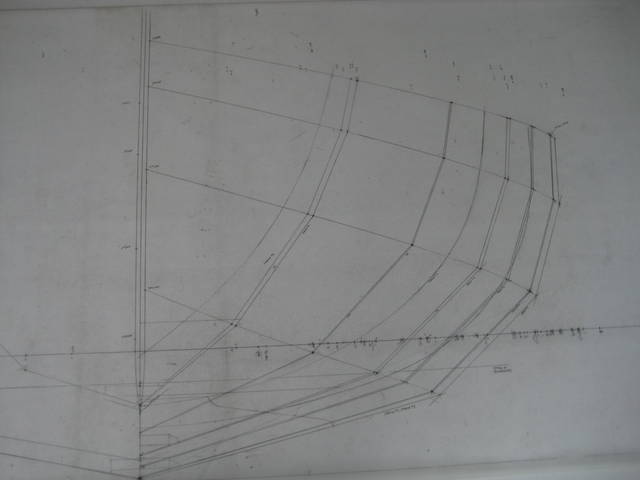
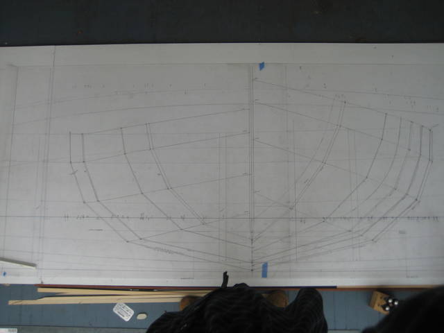
59 - It looks more like a boat now... |
|
60 - The nearly-complete body plan on top of the profile / half-breadth plan. |
|
61 - Laying out the carlin / coaming line. |
|
62 - The deck profile. |
|
63 - Starting the cabin crown and profile - use a quarter circle the height of the profile, divide it into four quadrants and use the height at each of these points to set the heights at each quarter of the width of the crown. |
|
64 - The quarter circle divided into four quadrants. |
|
65 - Setting a battern on the marks. |
|
66 - The keel plan is laid out both over and under the profile plan so that information from one plan can be put on the other. For example, the "bottom of boat" in the profile view is marked on the top of the deadwood in the keel plan. In addition, the keel bolts, frames and floors need to match. |
|
67 - The rudder plan. Note that the deck and cabin profiles are also on the left side of this sheet. One question from the plan is whether or not the "bottom of boat" is really the bottom of the inner keel (same as the lines) or the bottom of the planking. It really isn't clear, but on this plan, I used "bottom of planking and not "bottom of keel" but I think it very well could have been intended to be the other way. The net effect is that the keel and rudder will be moved approximately 3/8" one way or the other up and down. |
|
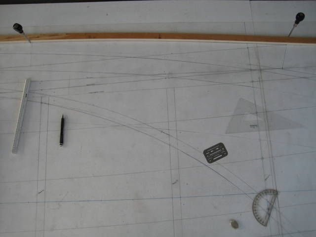
68 - The deck crown is laid out by applying the deck camber pattern to each frame/station in the body plan and the picking up the heights and putting them on the profile plan. |
|
69 - Another view of the deck centerline in the profile view. As you may be aware, using the same camber pattern for the whole deck will cause a dip of sorts as the boat gets narrower and the sheer rises. By laying out the complete profile now it can be seen if it is acceptable or if each deck beam needs to be drawn separately. |
|
70 - Deck centerline from the other direction. |
|
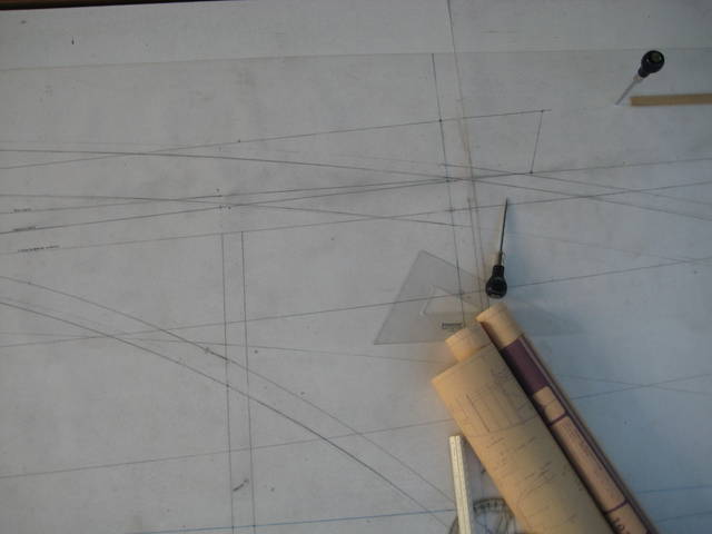
71 - This is a different day and the chart has been rolled out in the opposite direction. Here the deck/coaming line is being laid down. This line is found by using the coaming view in the half-breadth plan to find the distance from the centerline and then using these values to get the heights from the body plan. Once the heights are known, it can be plotted on the profile plan. |
|
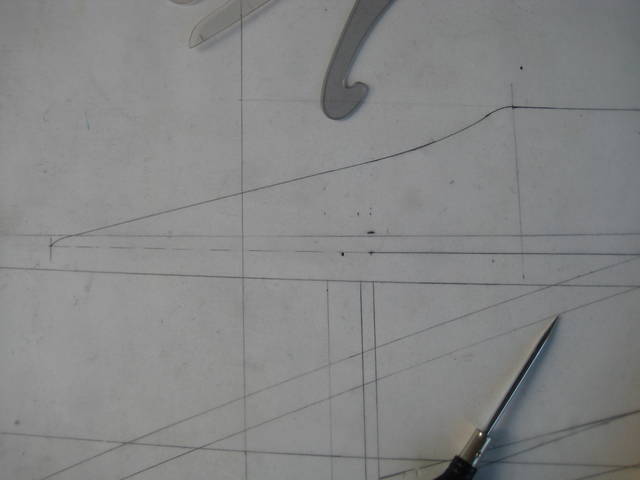
72 - A closer-in view of the decking/coaming line at the foremost end of the coaming. |
|
73 - The forward end of the coaming. |
|
74 - The aft end of the coaming. |
|
75 - Striking the cabin top line in profile. |
|
76 - It was time to go back and draw in the molded depth. |
|
77 - The forward end of the stern stem. |
|
78 - Back on the bow stem, the rabbet line has been drawn in (more detail later). |
|
79 - Looking closer in, the stem cross section is shown. |
|
80 - A little closer still. |
|
81 - Stern outer stem in profile. |
|
82 - This is the first of a sequence of pictures showing how to draw the stem cross section anywhere along the curve. The starting point is to draw a line roughly perpendicular to the stem face. |
|
83 - Looking at the same line, it can be seen that it was drawn at an offset point. |
|
84 - Step 2 is to draw the half width of the stem. The first line that was drawn is the centerline of the stem; this line shows the width of the stem. |
|
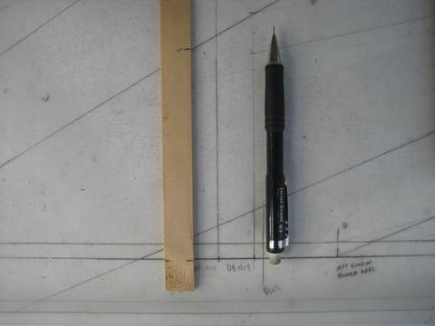
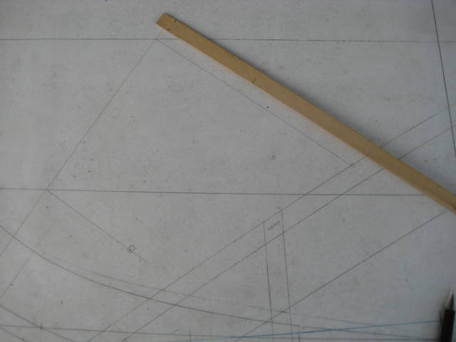
85 - The next thing is to mark the places along the stem centerline to mark the width of the hull. The first one here is where the plank lap line crosses. Here a piece of plywood is being used as a straight-edge to pick up the width from the half-breadth view. |
|
86 - A tick stick is used to record the width. |
|
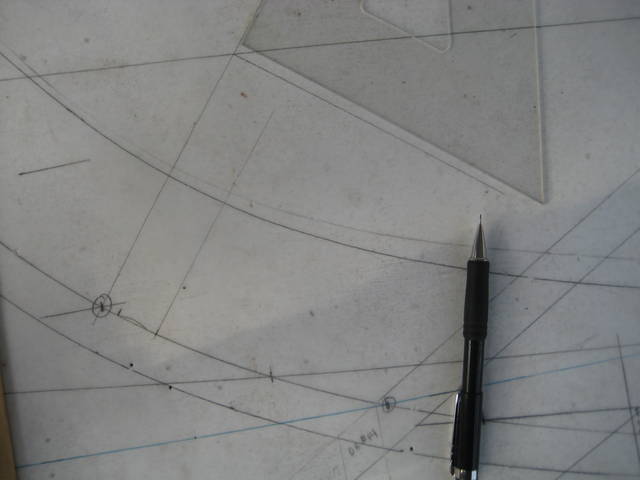
87 - Draw a line perpendicular to the center line at the point of intersection used to pick up the width from the half-breadth view. |
|
88 - On this line, mark the width using the distance that was marked on the tick strip. |
|
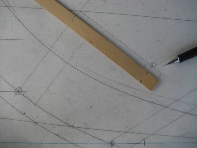
89 - Repeating the same process, except further away from the stem face. Here another plank line intersection in profile was used for convenience. |
|
90 - Use the square to get the tick strip properly oriented. |
|
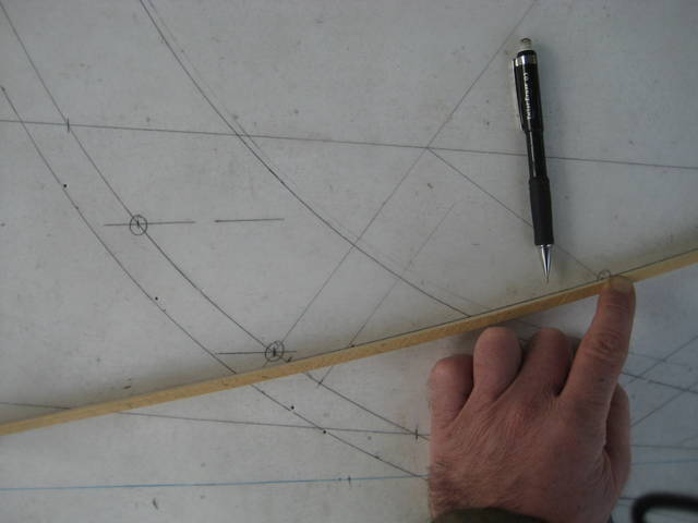
91 - The beam at this point is marked on the tick strip. |
|
92 - Then that distance is marked on the corresponding line perpendicular to the centerline. |
|
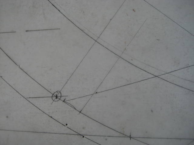
93 - Now a curve can be drawn using the two points picked up from the half-breadth view and the stem face width. |
|
94 - Here is that curve where it occurs on the stem. Note that there is no need to draw in the curve outside of the stem width, but I liked seeing the whole curve. |
|
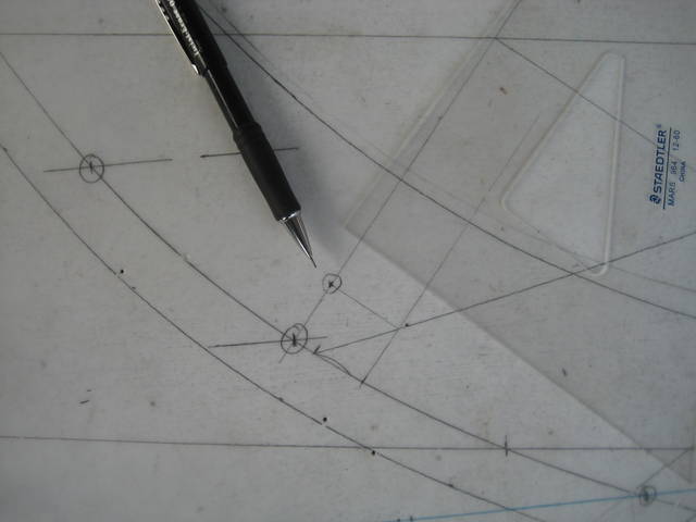
95 - Draw a line perpendicular to the stem width line at the point where the curve crosses it. What this does is to project the point that the plank (represented by the curve just drawn) meets the stem in profile view. Once a few of these points are obtained, a curve can be drawn in the profile view showing the rabbet line. (See #78, above). |
|
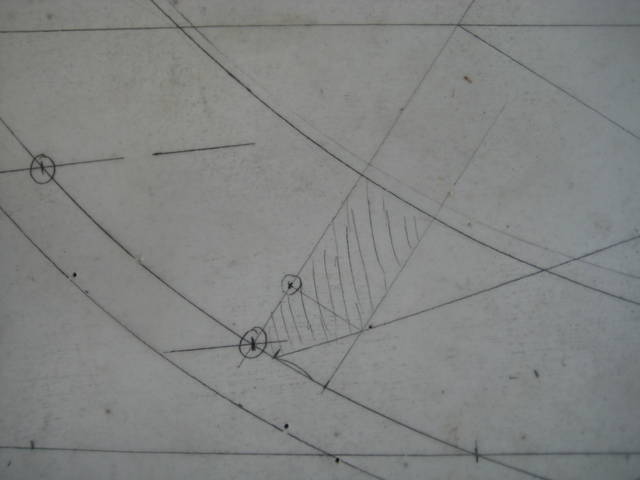
96 - With cross hatches, the stem cross section is easier to see. |